Where is my ECU?
Simply lift back the carpet adjacent to the centre console in the passenger foot well - picture
Why do I need to know the pin out/wiring diagram for the ECU?
When you modify your car then you are going to have to alter some of the signals being sent to, or, from the ECU, in order to increase the output power beyond the original design limitations, or alter the operation of a specific system. This may also be useful during fault finding.
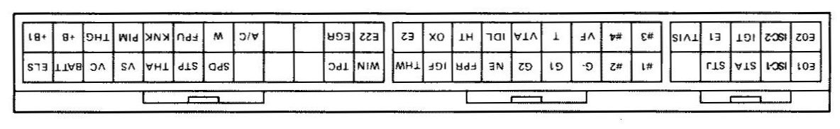
Righty-o! what's the layout?
Note that the ECU is installed "upside down". Therefore to make a direct comparison between the ECU and the diagram, the picture has been turned upside down - easier than trying to twist the ECU!
What do all those abbreviations mean?
Top row of pins on the ECU
| Abbreviation | Wire colour | Means... | What does it do? | Anything else? |
| E02 | White/Black | Earth | Attached to engine block | |
| ISC-2 | Green/Black | Idle Stabilisation Control | Opens a valve below the throttle body to control the idle speed rpm | Raises idle speed when aircon running, and when engine cold |
| IGT | White | Igniter signal | Controls spark to spark plugs, in effect fires the coil | |
| E1 | Brown | Earth | Attached to engine block | |
| TVIS | Light Green | Operates TVIS VSV | Opens a set of butterflies in the intake manifold at 4300rpm | |
| #3 | Yellow | Injector signal | Fires No 3 fuel injector | |
| #4 | Blue | Injector signal | Fires No 4 fuel injector | |
| VF | Violet/Yellow | Diagnostic connector | Check connector? | Any connections off? |
| T | Orange | Diagnostic connector | Check connector? | Any connections off? |
| VTA | White | Throttle position sensor | Informs ECU of throttle position | Very fine setup of the TPS sensor is required |
| IDL | Pink | Idle signal | Tells the ECU the car is at idle | Signal is from throttle position sensor |
| HT | Red/Green | To lambda sensor | 12V lambda sensor heater | Heats the lambda sensor to speed up a more accurate reading when the sensor is not up to operating temperature |
| OX | White | Lambda sensor voltage | A voltage feedback from the exhaust to "tune" the engine whilst at a steady rpm | Also feeds the OX pin at the diagnostic connector |
| E2 | Brown | Earth | ||
| E22 | Brown | Earth for AFM | ? | |
| EGR | Blue/Red | EGR VSV | Operates the EGR | |
| A/C | Black/White | Clutch relay signal | Engages the AC compressor magnetic clutch | |
| W | Green | Check engine light | Puts on the yellow engine check light | Indicates via a series of codes any stored faults |
| FPU | Black/Red | FPR control | Sends a signal to the fuel pressure VSV to increase the fuel pressure | Only the 165 has this arrangement... |
| KNK | Clear | Knock sensor | Sensor feeds in a voltage to the ECU proportional to the amount of knock in the engine... | If knock is sensed then the ignition timing is retarded |
| PIM | Red/White | TPS voltage | Feeds a voltage to the ECU proportional to the boost pressure | This signal is altered with an FCD if you want to run high boost. Also controls the dash boost gauge. A lot of websites/articles/books call this the P/M - they didn't read the connections carefully, it should be the PIM signal. In fact Toyota have made this mistake in some of their workshop manuals |
| THG | Blue | EGR temp sensor | Not fitted in UK | Only fitted to USA cars |
| +B | Black/Yellow | 12V supply to ECU | 12V fed after ignition key is turned | |
| +B1 | Black/Yellow | 12V supply to ECU | 12V fed after ignition key is turned | Good place to attach items that you don't want to stay on after engine turned off e.g. BG light |
Bottom row of pins on the ECU
| Abbreviation | Wire colour | Means... | What does it do? | Anything else? |
| E01 | White/Black | Earth | Attached to engine block | |
| ISC-1 | Green/White | Idle Stabilisation Control | Opens a valve below the throttle body to control the idle speed rpm | |
| STA | Black | Starting signal | 12V fed to the ECU whilst the car is trying to start | |
| STJ | Green | Cold start injector | Signal to control the 5th injector when starting the car | |
| #1 | Red/Black | Injector signal | Fires No 1 fuel injector | |
| #2 | Light Green | Injector signal | Fires No 2 fuel injector | |
| G- | Red | Distributor signals | Ground for G1, G2 and NE | |
| G1 | Dark Green | Distributor signals | Sends crankshaft angle information | Allows ECU to determine the position of each piston, adjust injector and ignition timing |
| G2 | White | Distributor signals | Sends crankshaft angle information | As above, but 180o out from G1 |
| NE | Black | Engine rpm signal | Sends the engine speed and crankshaft angle to the ECU | Positive signal from 24 tooth sensor |
| FPR | Blue/Red | Fuel Pump Relay | Clicks on the fuel relay when you turn the ignition key | If it doesn't activate the fuel relay the car won't start |
| IGF | White/Red | Spark confirmation signal | Used to detect a fault within the igniter | |
| THW | Red | Water temperature sensor | Informs ECU of water temperature | Probably used to correct fuel and ignition maps |
| WIN | Light Green/Black | Intercooler computer signal | Error reporting? | |
| TPC | Black/White | TVSV signal | Allows extra boost in 3+ gears ~2psi | Don't cut this wire, pull the pipe off from the wastegate actuator instead! |
| SPD | Blue/White | Speed sensor | Monitors car speed | |
| STP | Green/White | Stop light switch | Monitors the brake light switch | To inform the ECU when braking, to apply deceleration fuel cut |
| THA | Grey | AFM air intake temp | Tells the ECU the temp of the incoming air | |
| VS | Grey/Black | AFM signal | Stopped - idle signal | |
| VC | Pink/Blue | AFM signal | Variable - flap position signal | |
| BATT | Pink | Battery supply | Supplies power to ECU via the 15A engine bay fuse | Permanent 12V feed to the battery even when the ignition is off |
| ELS | Orange | Electrical idle up | Increases idle speed due to large current drawn by headlights and demister |
Notes
Want a print out the ECU diagram and pins for a handy reference? Click on the download button below. Note that the ECU pin outs have been altered to the correct way around as you are looking at the ECU.
| Updated 31/08/05 Word Document ~172k |