What is an FCD?
Have a look at my what is an FCD article
How easy is this to make?
Depends if you have any experience with electronics and soldering. Just take your time and use a small soldering iron, either a 12W or 25W
Can I fit this to a 205?
No - because the 205 uses the TPS/MAP sensor to help work out fuelling and ignition. Mess with this signal and you are asking for trouble. The 165 and 185 are not fitted with a MAP sensor which is used to work out fuelling and ignition in the same way as the 205, the 165 and 185 calculate their fuelling and ignition timing differently...
Do I need to fit anything else before the FCD?
No. But you'd probably want to be doing this in conjunction with raising your boost level. If you are raising your boost level then a boost gauge and some way to increase your boost e.g. SBC or RV would be required. Fitting an FCD without anything else is pointless.
What do I need to know before I start?
What tools do I need?
Where is the FCD fitted?
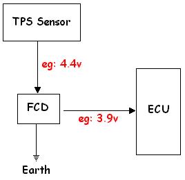
The unit is fitted inline between the TPS and ECU. The unit takes the TPS signal and feeds out a modified signal as it bleeds off a portion of the signal to earth. Therefore 3 connections need to be made to install this unit.
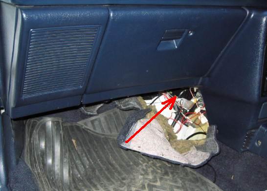
The FCD is inserted between the TPS and the ECU wiring as shown below, pictures from 165...
 |
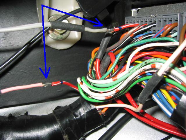 |
| ECU located under dash. The carpet just lifts back | Insert the FCD in the Red with White stripe wire |
Note the connections have been soldered, not crimped or worse "choc blocked". Note the rubber sleeve on the top grey wire. This is slide down the wire to insulate the bare connection. Insulating tape in my opinion is only a temporary measure. You want a reliable car!
To install - simply cut the "PIM" wire (Red/White stripe) running to the ECU approx 2 inches from the ECU and solder the FCD in place as in the picture above. ECU pin out diagram here. Leave approx 18 inches of wire to the FCD so that you can easily adjust it. Don't forget to connect the earth wire to a ground e.g. via a crimp to the ECU mounting bolts.
Okay I want to be safe and retain the fuel cut. How do I make an FCD?
Parts
Take your veroboard and construct the circuit as shown below, soldering the components to the veroboard - looks a bit messy but I was "experimenting!"
When assembled it should look something like this:
 |
 |
 |
| Rear of FCD | Completed FCD ready to be placed within film canister | FCD within it's case |
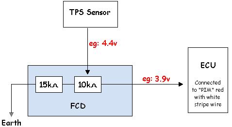
What's the theory behind the circuit?
The theory is simple. All FCDs alter or bodge the voltage signal from the TPS. The resistor method drains a portion of the signal away down to earth. i.e. part of the signal produced by the TPS will be taken away. This is done through a potential divider network. The single fixed resistor is in place to ensure there is always part of the signal to be drained down to earth and so that you cannot short out the signal being sent from the TPS and potentially damage the TPS or ECU. The variable resistor is used to set an alterable point at which you want fuel cut to happen.
How do I set it up?
If you don't have a boost gauge, get one. Do not proceed any further until you have a decent boost gauge. This is vital in initially setting up your car and seeing what is happening. Without a Boost Gauge, how on earth are you going to see what boost pressure you are running? Fitting instructions here
Done by example...you want to run 15psi...
What boost can I run safely?
You're gonna have to make your own mind up on this one. Personally I'd say no more than 10psi on a stock 165, 12psi on a stock 185 and 16psi on a stock 205.
Opinions vary on the pressures and they're my 2p, and as I say, read the disclaimer...
Disclaimer
Indiscriminately turning up your boost may well lead to engine failure. This guide is written as an informative article only as to how I managed to overcome fuel cut. If you turn up your boost level that's entirely up to you. Running a higher boost level will shorten the life of your engine. If in any doubt consult a qualified mechanic. Increasing the boost pressure of your turbo beyond the design limitations of the manufacturer is not recommended and may result in engine damage, but it may make you smile!